
Titre du Projet
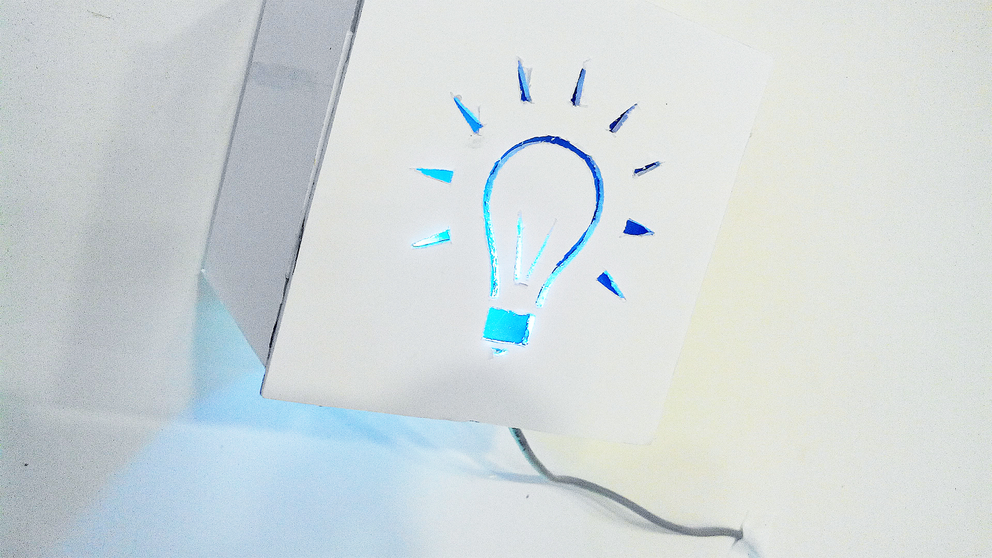
Light Box
Auteur
AGAM Maya, ALONI Chen, ROGALSKA Valeria
Intentions / Contexte
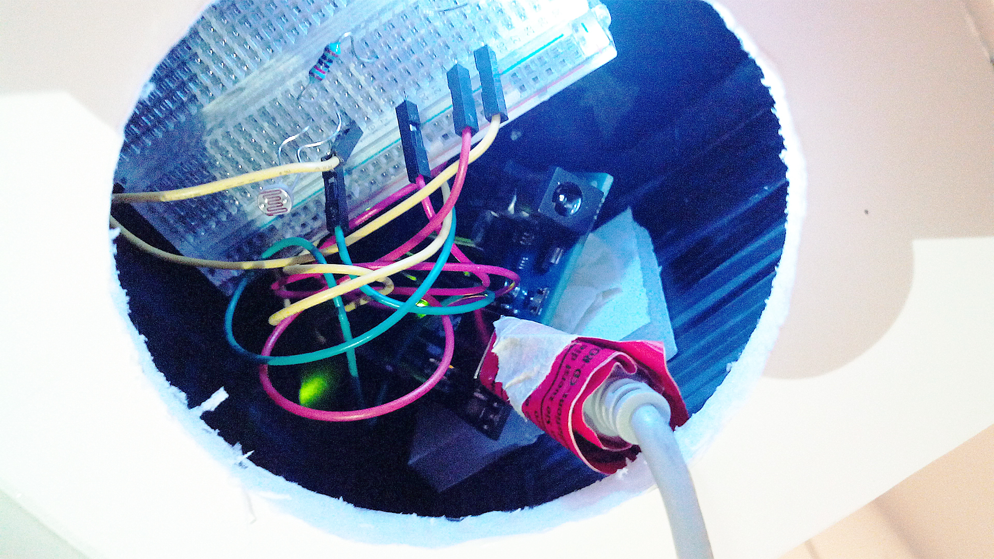
Principe de Fonctionnement
/*
Analog input, analog output, serial output
Reads an analog input pin, maps the result to a range from 0 to 255
and uses the result to set the pulsewidth modulation (PWM) of an output pin.
Also prints the results to the serial monitor.
The circuit:
* potentiometer connected to analog pin 0.
Center pin of the potentiometer goes to the analog pin.
side pins of the potentiometer go to +5V and ground
* LED connected from digital pin 9 to ground
created 29 Dec. 2008
modified 9 Apr 2012
by Tom Igoe
This example code is in the public domain.
*/
// These constants won’t change. They’re used to give names
// to the pins used:
const int analogInPin = A0; // Analog input pin that the potentiometer is attached to
const int analogOutPin = 9; // Analog output pin that the LED is attached to
int sensorValue = 0; // value read from the pot
int outputValue = 0; // value output to the PWM (analog out)
void setup() {
// initialize serial communications at 9600 bps:
Serial.begin(9600);
}
void loop() {
// read the analog in value:
sensorValue = analogRead(analogInPin);
// map it to the range of the analog out:
outputValue = map(sensorValue, 0, 1023, 0, 255);
// change the analog out value:
analogWrite(analogOutPin, outputValue);
if (sensorValue < 260){
digitalWrite(9,LOW);
delay(30);
digitalWrite(9,HIGH);
delay(100);
digitalWrite(9,LOW);
delay(30);
digitalWrite(9,HIGH);
delay(70);
digitalWrite(9,LOW);
delay(30);
digitalWrite(9,HIGH);}
// print the results to the serial monitor:
Serial.print(« sensor = » );
Serial.print(sensorValue);
Serial.print(« \t output = « );
Serial.println(outputValue);
// wait 2 milliseconds before the next loop
// for the analog-to-digital converter to settle
// after the last reading:
delay(2);
}
Besoins / Compétences
llustration / Schéma
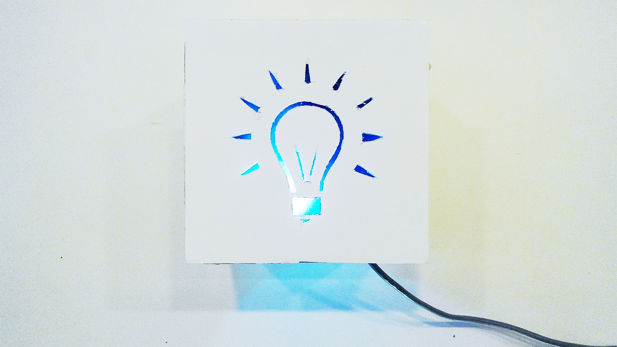
Light box from Studio Objet Augmente on Vimeo.